

Dredger Operation
 Product overview
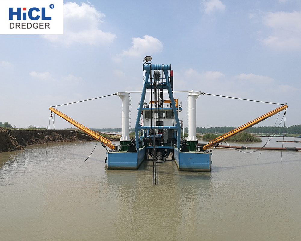
The varieties of dredgers are cutter suction dredger, bucket wheel dredger, grab dredger and jet suction dredger. They are absolutely necessary widely used, efficient and cost-saving tool in modern production and are mainly used to desilt and deepening channel, excavate and maintain waterways, expand shoreline or create land and pumping sand. In these dredging equipments, cutter suction dredger is of higher efficiency.
Working principle
The engine of the dredger provides power, then the gear box will transit it to the sand pump, the former is driven to rotate and create vacuum in suction pipe. In this way, the mixture composed of mud, sand and water and cut by the cutter head or bucket wheel is sucked into the sand pump through the inlet pipeline, and then discharged by the pump to the appointed place through outlet pipeline which is connected to the outlet of the sad pump.
Structure and component
Hull
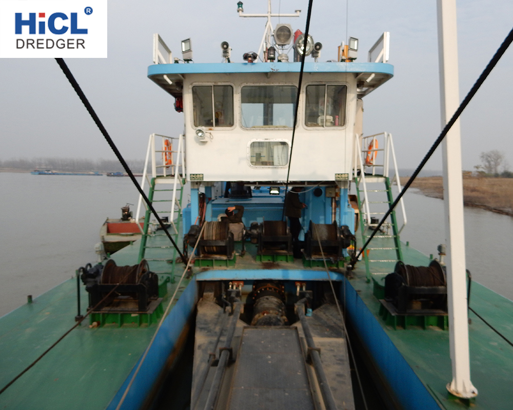
The hull is made of three pontoons –One main pontoons and two side pontoons, that is a wider main pontoon in the middle, carrying diesel engine and pump - to which two side pontoons as flotation tank are connected by pothook in the lower part and connecting board through high strength bolt in the upper part. This structure is of reliable stability.
Function of the main pontoon: to guarantee a certain buoyancy and provide a place to install equipment, such as main engine, gear box, sand pump, main generator set, auxiliary generator set, hydraulic oil tank, electrical system, hydraulic pump, starting system, recycling cooling system for hydraulic system motor, and other pumps.
Function of side pontoon: to guarantee certain buoyancy and carry fuel tank, fresh water tank, storage, and air tank.
Deck
The deck is equipped with engine cabin, operating room, deck crane, toilet, hydraulic cylinder, reverse spud frame, left traverse winch, bridge winch, right traverse winch and frame A of bridge lifting.
The engine cabin is consisting of pipeline, main engine expansion tank, skylights, ventilation fans, silencers.
The operating room is a workplace for the dredger operators, which is equipped with operating cabinets, instruments, electrical cabinets, air conditioning and other equipments.
The deck crane, installed beside the sand pump, is a kind of lifting equipment with cantilever and mainly used as a tool when repairing the sand pump and replacing the wearing parts.
The main function of the left and right traversing winches is made the dredger moving from left to right as a fan-shape.
Left (Right) traversing winch is used to wrap wire line around the winch drum, and provides power to make the dredger move left by tensioning the wire rope. The other end of the wire rope goes through the left pulley fixed on the ladder bridge and fastens on the anchor. The angle between the center line of the dredger and wire rope is required to be 65~80 degrees. The position anchor should be 50 meters left (right) away from the dredger under water. (Anchoring distance depends on your working condition, if the condition allows, the further it is, and the steadier the anchor is.)
Lifting bridge winch, working in the same way as the traversing winches, the wire rope going through a pulley block which fixed on the A frame and ladder bridge respectively, using to lifting the ladder bridge, so as to control the depth of dredging work.
The engine drives the hydraulic pump to provide power to hydraulic system, and the power, through hydraulic oil tank and hydraulic pipeline, is transmitted to the hydraulic components and drives the left traversing winch, right traversing winch and lifting winch to work.
The operator can control electromagnets power on and power off by operating the change-over switch button on operation panel to make the winches retrieve and release the wire rope.
The ladder bridge and the cutter head part is mainly made of ladder bridge steel structure, suction pipe, left and right traversing pulley, ladder bridge ascending and descending pulley block, hydraulic pipe, cutter head, cutter head driving hydraulic motor, gear box etc.. The ladder bridge is fixed on the main pontoon by two axle pins. Its main function is to install suction pipe and make the cutter head descend to certain depth and cut sand.
Spud parst
Two spuds, two hydraulic cylinder, and two down pile frame. Spuds are steel hollow cylinders which are customized according to average draught, water flow and dredging depth of the dredger.
The main function of spuds is to fix the dredger in certain point and provide a fulcrum for the dredger to do fan-shape movement. There is two type of moving forward during construction: one is alternately use the spud during the fan-shape movement, the other is pushing the spud forward directly.
There are two spuds, main spud and vice spud. During construction processing, only one is inserted into the sand. Two spuds are inserted at the same time is not allowed.
The spuds are fixed on the stern with hoops. Down pile frame is auxiliary equipment used to erect and put down the spuds.
Situations that need put down the spuds: when moving from one work site to another work site, there are bridges, electrical obstacles of the voyage; when meeting seven storm winds during construction. The spud is only being erected when enter the work site and prepare to start work. (The process to erect and put down the spud is risky, pay more attention to personal safety.)
Cutter head
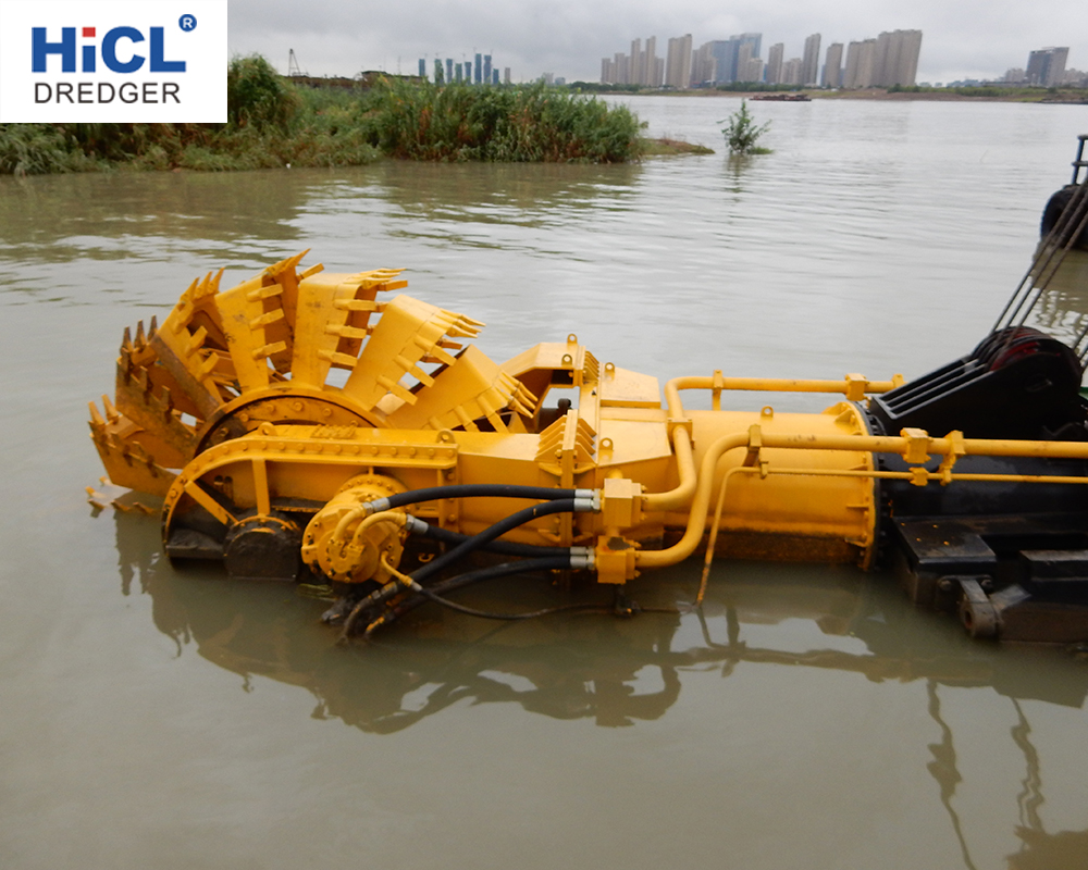
The ladder bridge and the cutter head part is mainly made of ladder bridge steel structure, suction pipe, left and right traversing pulley, ladder bridge ascending and descending pulley block, hydraulic pipe, cutter head, cutter head driving hydraulic motor, gear box etc.. The ladder bridge is fixed on the main pontoon by two axle pins. Its main function is to install suction pipe and make the cutter head descend to certain depth and cut sand.
The dredger are composed of five system
Hydraulic system, electrical system, cooling and fire system, flushing system, dredging power system, sand discharging system and starting system.
Hydraulic system
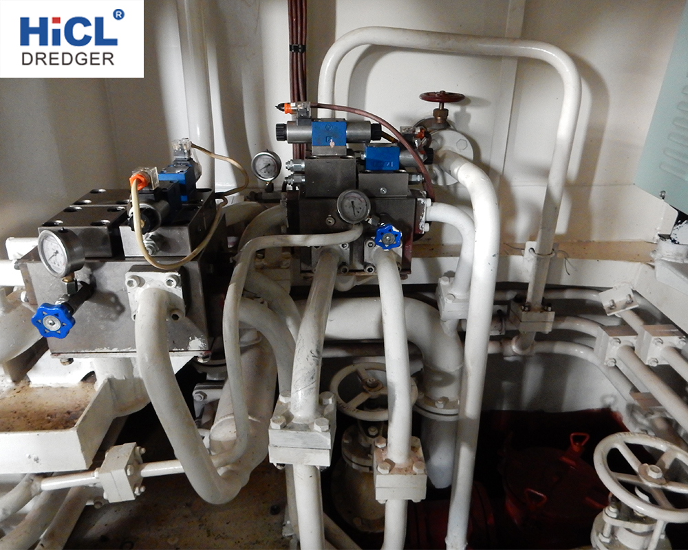
Hydraulic system: the most important parts of cutter suction dredger and wheel bucket dredger. The hydraulic system requirements are very high, and strict; it’s the main artery of the entire dredger.
An integral hydraulic system includes hydraulic oil tanks, hydraulic pump, hydraulic valve manifold, solenoid valve, hydraulic pipes, hydraulic components, electrical actuator and so on.
Among them on pressure regulator is used to control left / right traverse winch manifolds, ladder bridge winch manifold and spuds manifold and adjust the pressure of the system. Besides, we install an emergency hydraulic pump group in the system; it is mainly used for maintenance, adjustment and other emergency conditions, when the engine and the gearbox fail to work, and it can achieve full functions of the hydraulic system, but it can not be used for normal production.
Introduction for hydraulic valves maintaining
Next, we introduce the function of each manifolds, and common trouble shooting ways.
Left / right traverse manifolds: using to control the left / right traverse to release or retrieve wire line.
Ladder bridge lifting winch manifolds: using to control cutter frame to ascend or descend, and composed of electro-hydraulic change valve and balanced valve.
Spud manifolds: the slow release of the stern pile is controlled by throttle needle valve.
The manifolds is used to control the left and right spud to ascend and descend, and composed of solenoid valves and pilot controlled check valve.
If the above mentioned manifolds fail to move, it may have the following cause,
※ The electro-hydraulic valve blocked, in this case, please remove the valve and wash it with clean diesel, then reinstall it according to what it is before.
※ Solenoid valve is not energized; please check if the circuit is breakdown or not.
※ Solenoid valve coil damaged, please replace the coil.
Note: The above failure may be caused by the internal damage of hydraulic motor that drives winches.
Cutter pressure adjustment manifolds: There are two pilot relief valves which are used to control hydraulic pump pressure and drive the cutter to rotate. If the cutter lost pressure, it may because by the following reasons.
※ The pilot relief valve blocked, in this case, please remove the valve and wash it with clean diesel, then reinstall it according to what it is before.
※ Pilot relief valve is not energized; please check if the circuit is breakdown.
※ Solenoid valve coil damaged, please replace the coil.
Miscellaneous pressure adjustment manifolds as follows
Its functions have been introduced above; here we introduced the adjustment method and fault processing method.
※ Miscellaneous relief valve has a rotating handle, when rotating clockwise, pressure rises; when rotating counterclockwise, pressure drops. The pressure adjustment range is 8~10Mpa. If the other systems have no action except the cutter, this may caused by following reasons
※ The pilot relief valve blocked, in this case, please remove the valve and wash it with clean diesel, then reinstall it according to what it is before.
※ Pilot relief valve is not energized; please check if the circuit is breakdown.
※ Solenoid valve coil damaged, please replace the coil.
Besides, there are another two valves: 1. flow control valve 2. left traverse back pressure regulating valve.
※ Flow control valve, which is installed in series in the pipe of left/right traverse winch system, is used to adjust the speed (according to your needs) of left/right traverse winches.
Left traverse back pressure regulating valve: used to control the winch to retrieve or release wire line by adjust the pressure of oil return pressure. Cutter suction dredger cuts and breaks sand with its cutter head, when the dredger make fan-shape movement to the left, we call it anti-knife; on the contrary, when the dredger move to the right, we call it syn-knife.
The difference between anti-knife and syn-knife is: when cutting harder sandy soil, syn-knife may slide through it and reduce cutting effect; instead, there is a cutting resistance to make anti-knife avoid sliding cutter. In order to avoid sliding cutter and improve cutting efficiency, back pressure valve is applied to increase pressure on syn-knife.
Applications of main generator: providing electricity for seal water pump, miscellaneous pump, lighting, air conditioning.
Applications of standby generator set: providing electricity for the above equipment when the dredger stopping working, or maintenance, or meeting an emergency condition.
Charger: using for accumulator charging
Battery: provides electricity for diesel engine starting, hydraulic solenoid valve closing, 24v lighting and signal light.
Electrical cabinet: used to control electrical equipments on board and include generator, knife switch, seal water pump, miscellaneous pump, hydraulic pump, fan, air-break switch for lighting, air switch and earth leakage protection
devices. On the panel, there are voltage dial gauge; working and emergency generator transfer switches; start /stop buttons for emergency hydraulic pump, sand pump, sealed pump, miscellaneous pump, and fans.
Operation platform configuration as follows:
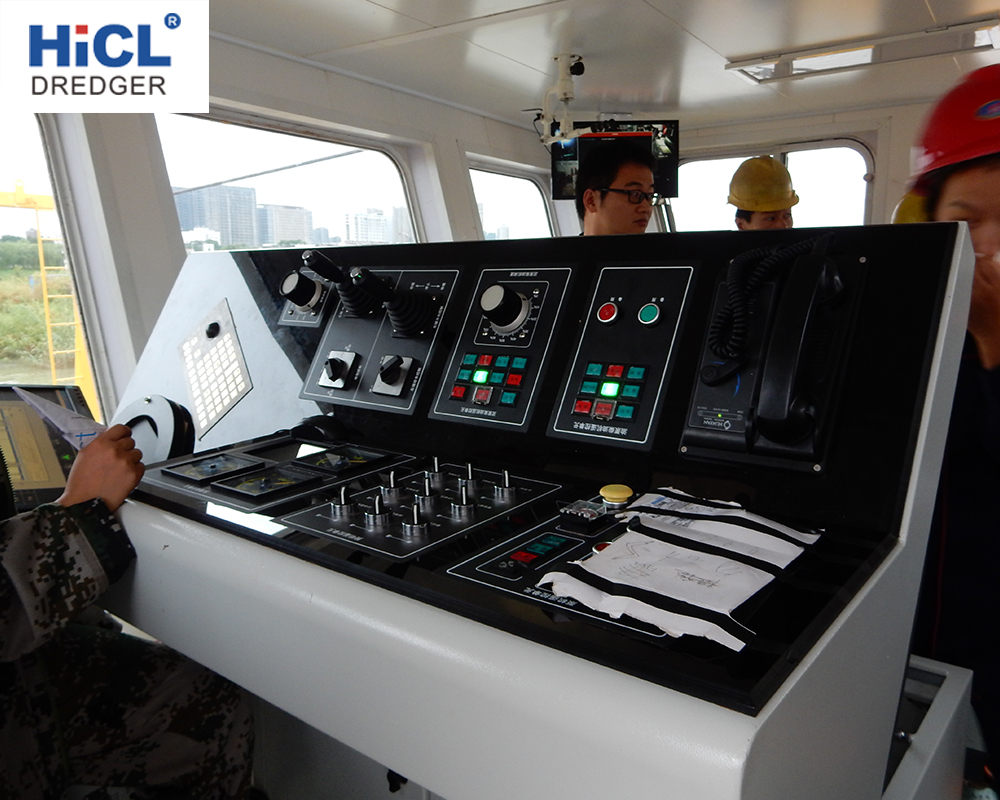
1. Main switch knob: turn on / off 24v power source in the operating desk.
2. Cutter switch and turning machine for alignment switch: for dredger bugging, and cutter repairing.
3. Left and right traversing winch switches: for dredger does fan-shaped movement.
4. Cutter ladder button: using for ladder raising and lowering to control the dredging depth.
5. Cutter head switch: for cutter head rotating and controlling tap position.
6. Mud pump switch: using to control the gearbox get row and off row, controlling pump start and stop
7. Right spud and left spud switch: for spud raising and lowering control.
8. Engine monitoring meter: for engine checking in the working process.
9. Back pressure control valve: using to adjust size of left traversing back pressure.
10. Meters : miscellaneous gauge, cutter head pressure gage, discharge pressure gauge, vacuum gauge.
11. Miscellaneous gauge: using for pressure showing of hydraulic system and hybrid system, usually it can be adjusted from 8 ~ 12Mpa.
12. Cutter head pressure gage: using for pressure showing of hydraulic system and cutter head, usually it can adjusted from 8 ~ 12Mpa.
13. Discharge pressure gauge: using for pressure showing of pipeline discharging. Usually when it is the max. discharge distance and good concentration, the pressure is about 0.5MPa.
14.Vacuum gauge: using for concentration showing tube in the discharge pipe. Generally it is around 0.04 ~0.06Mpa.
Operating specifications and procedures:
Firstly, before the dredger working, it is a very important to check the following goods complete or not : life jackets, lifebuoys and other life-saving equipment and sand boxes, fire buckets, fire extinguishers. Working safety is everyone's responsibility.
Comprehensive inspection before launching the new dredger as follows:
hull seepage or not, whether the connections are tightly fixed or not, screws installed or not, screw accessories are enough or not. (Note: dredger in our company is dismantle type, so pay attention to the above-mentioned parts); When dredger working check water leakage or not of the dredger main pontoons, side pontoons, each compartment and cabin. All of these checking working done, this dredger can be working at the working site(Note: dredger in our company has been tested before ex-factory for the mentioned conditions).
Matters need attention steps and precautions before dredger working are as follows: first to lubricate all points of the dredger with butter and lubricating oil; diesel fuel tank filling (Note: diesel oil standard model is given according to the local climate and environment.) Adding water to engine internal recycle to the specified range (Note: antifreeze added in the cold zone, adding water to the scale of 3/4 expansion tank, sometimes may be at the highest of level gauge).
Adding hydraulic oil to the hydraulic tanks of the hydraulic system, oil is to be the top of hydraulic level gauge.
Hydraulic oil selection: when ambient temperature is below 20 degrees Celsius, anti-wear hydraulic oil(L-HM46); when it is 20 to 30 degrees Celsius L-HM68 needed, when is more than 30 degrees Celsius, 100 L-HM100 is good. Temperature of working hydraulic system is less than 90 degrees Celsius.
Grease filling points as following: pulleys on the ladder bridge, left and right traverse pulleys, A-frame pulleys, bridge connection axis between ladder bridge and main pontoon, lifting pulley axle pin and the fuel tank base axle pin.
Engine oil adding points:
1. bearing box of cutter head,
2. hybrid pump bearings base,
3. sand pump bearing boxes (in two forms: butter filled, engine oil filled),
4. gearbox,
5. engine (Note: engine oil added according to gearbox and engine manual).
Preparation before starting the engine
Firstly, checking cycle water level inside the engine; secondly, checking hydraulic oil tank and opening the tank outlet valves; thirdly, checking oil lever of engine, gearbox, sand pump, and bearing boxes; fourthly, opening seabed valves outside circulating water system, adjusting all valves under working condition. Such as, jet water pump, miscellaneous pump, sea water pump and so on; and finally going to operating cabin to view all switch buttons are on the stop state. (Disconnect the 24v power supply), ensure all that is in the very condition, and then opening the knife switch under the engine room, last starting the engine (start engine is available in two configurations, one is electric start, the other is gas start.)
Matters Need Attention/Attentions
Starting the engine, idle running about 10 minutes, only when water temperature, oil temperature and oil pressure meet requirement, the dredger begins to work. (Note: specific requirements according to the onboard engine manual). Before Engine drives the sand pump to work, opening 24v power supply master switch in the operating cabinet, rotating ladder bridge button to have ladder bridge winch down, and having ladder bridge, sand pipeline and cutter head submergence into the water; and then start the jet water pump for water pumping; thirdly rowing on through row button on the operating desk; at that time engine drives gear box and sand pump to work, and slowly increasing rotating speed of engine to required speed. (Note: only at the lowest rotating speed, the row switch can be turn on; at high speed, is definitely allowed to turn on). In the state there is water flows from pipeline, the dredger can do the daily working. (In the working process, when dredger does the fan movement, two spuds are not allowed to insert into mud at the same time). When sand pump needs to be suspend, it musts at the minimum speed and then off row will be successfully.
Note that in the working process, workers in the cabin need to observe the cabin inside situation through smell, listen, look, and touch etc.
※ Smell, whether there is peculiar smell or not;
※ Listening, if there is abnormal sound;
※ Supervising monitoring instruments is normal or not, hydraulic system is leaking or not, cooling system leaking or not, engine leakage or not (water leaks, oil spills, air leakage)
※ Touching shell to feel temperature high or not, vibration strong or not.
Dredger working process classification as follows
※ dredger starting work
※ dredger working process
※ dredger ends its work
Dredger starting work as follows:
Preparation work before the dredger starting.
Firstly, arranging workers to the working site to measure water depth and working environment by service ship. Because for spud erecting, the water depth must be deep enough. If both are met, tugging the dredger to the working site and erecting the spuds. Secondly, start the standby generator set, having the hydraulic system to work properly through emergency hydraulic pump, releasing traverse mooring ropes on right and left, having them bypass the sliding pulley on the ladder bridge; then leading the wire rope through back of the main pontoon anti sent to spud roots for one perimeter and fixed; thirdly, according to the terrain, making the ladder bridge to the deepest water depth (depth of not more than dredging depth); at the time, starting the traverse winches, slowly closing mooring rope to let spud slowly erected, this including right mooring rope for right spud, and left one for left spud.
Special Attention to safety and staff need to avoid rope suddenly disconnected from the spuds. After spud erected, connecting wire rope on the spud, then having the wire rope connected to the wire rope of hydraulic cylinder, applying hydraulic cylinder to adjust to the very height to the construction area, put down the spud to make dredger insert into the mud for fixing, so with the normal start-up procedure to start the engine, traverse winches to put anchor for locating.
Construction on working site, concentrate seriously on operations:
Working environment condition is not more than 6 wind velocity; water flow is not too bigger, also pay attention to where there is tide. All the above aspects satisfied, dredger can start working. In the working process, should be noted that the spud lifting height, especially do not allow the two spuds insert into mud at the same time. Pay attention to running conditions of engine and hydraulic system. Besides, observe all instruments, if there is sailing ship, pay attention to its movement.